CN100412486C - Substrate drying apparatus and substrate drying method - Google Patents
Substrate drying apparatus and substrate drying method Download PDFInfo
- Publication number
- CN100412486C CN100412486C CNB200410055261XA CN200410055261A CN100412486C CN 100412486 C CN100412486 C CN 100412486C CN B200410055261X A CNB200410055261X A CN B200410055261XA CN 200410055261 A CN200410055261 A CN 200410055261A CN 100412486 C CN100412486 C CN 100412486C
- Authority
- CN
- China
- Prior art keywords
- substrate
- exhaust apparatus
- air
- cowling panel
- drying device
- Prior art date
- Legal status (The legal status is an assumption and is not a legal conclusion. Google has not performed a legal analysis and makes no representation as to the accuracy of the status listed.)
- Active
Links
Images


Classifications
-
- F—MECHANICAL ENGINEERING; LIGHTING; HEATING; WEAPONS; BLASTING
- F26—DRYING
- F26B—DRYING SOLID MATERIALS OR OBJECTS BY REMOVING LIQUID THEREFROM
- F26B21/00—Arrangements or duct systems, e.g. in combination with pallet boxes, for supplying and controlling air or gases for drying solid materials or objects
- F26B21/004—Nozzle assemblies; Air knives; Air distributors; Blow boxes
-
- B—PERFORMING OPERATIONS; TRANSPORTING
- B08—CLEANING
- B08B—CLEANING IN GENERAL; PREVENTION OF FOULING IN GENERAL
- B08B3/00—Cleaning by methods involving the use or presence of liquid or steam
- B08B3/04—Cleaning involving contact with liquid
- B08B3/10—Cleaning involving contact with liquid with additional treatment of the liquid or of the object being cleaned, e.g. by heat, by electricity or by vibration
-
- F—MECHANICAL ENGINEERING; LIGHTING; HEATING; WEAPONS; BLASTING
- F26—DRYING
- F26B—DRYING SOLID MATERIALS OR OBJECTS BY REMOVING LIQUID THEREFROM
- F26B15/00—Machines or apparatus for drying objects with progressive movement; Machines or apparatus with progressive movement for drying batches of material in compact form
- F26B15/10—Machines or apparatus for drying objects with progressive movement; Machines or apparatus with progressive movement for drying batches of material in compact form with movement in a path composed of one or more straight lines, e.g. compound, the movement being in alternate horizontal and vertical directions
- F26B15/12—Machines or apparatus for drying objects with progressive movement; Machines or apparatus with progressive movement for drying batches of material in compact form with movement in a path composed of one or more straight lines, e.g. compound, the movement being in alternate horizontal and vertical directions the lines being all horizontal or slightly inclined
-
- H—ELECTRICITY
- H01—ELECTRIC ELEMENTS
- H01L—SEMICONDUCTOR DEVICES NOT COVERED BY CLASS H10
- H01L21/00—Processes or apparatus adapted for the manufacture or treatment of semiconductor or solid state devices or of parts thereof
- H01L21/67—Apparatus specially adapted for handling semiconductor or electric solid state devices during manufacture or treatment thereof; Apparatus specially adapted for handling wafers during manufacture or treatment of semiconductor or electric solid state devices or components ; Apparatus not specifically provided for elsewhere
- H01L21/67005—Apparatus not specifically provided for elsewhere
- H01L21/67011—Apparatus for manufacture or treatment
- H01L21/67017—Apparatus for fluid treatment
- H01L21/67028—Apparatus for fluid treatment for cleaning followed by drying, rinsing, stripping, blasting or the like
- H01L21/67034—Apparatus for fluid treatment for cleaning followed by drying, rinsing, stripping, blasting or the like for drying
Abstract
Provided is a drying device for extremely reducing a quantity of liquid on a surface of a substrate to become a mist to scatter. The liquid attached to the upper surface of the substrate W carried on a carrying roller 2 is pressed in a gap between the upper surface of the substrate and an upper straightening vane 10 by air from an upper air knife 11. The pressed liquid is pressed out along the upper surface of the substrate toward one side as the upper straightening vane 10 is disposed in a tilted manner by an air flow produced between the upper surface of the substrate and the upper straightening vane 10 and the air from the upper air knife 11, and eventually flows from the upper surface of the substrate W toward an upper exhaust means 6 to be disposed of outside the drying device.
Description
Technical field
The present invention relates to a kind of apparatus and method of substrate surfaces such as glass substrate or semiconductor wafer being carried out drying.
Background technology
Before applying resist liquid or SOG liquid on the substrate surface, the past all will be cleaned substrate surface earlier.Owing to making clean surperficial air dry need the time, therefore in patent documentation 1 and patent documentation 2, disclose and adopted air knife to make the technology of dry tack free.
Patent documentation
Patent documentation 1: open flat 2-44327 communique Fig. 1 in fact
Patent documentation 2: the spy opens flat 7-35478 communique paragraph [0008]
Summary of the invention
There is following problem in above-mentioned patent documentation 1,2 disclosed contents: owing to all be to peel off liquid by the force air ground from the air knife ejection from substrate surface, and utilize attraction pipeline to get rid of this liquid, therefore in attraction pipeline, there is not captive liquid to dance in the air at periphery, and become fog and be attached to inner surface of device etc., and become particle once more and be attached to substrate surface.
For addressing the above problem, substrate drying device according to the present invention comprises: the top exhaust apparatus of the air in the transport path of discharge substrate; With the throughput direction of substrate be benchmark with respect to described top exhaust apparatus the downstream configuration, forming the top cowling panel in the gap that makes the air upstream side flow with the space above the substrate; Abut against that the downstream is provided with, as on conveying substrate, upstream to blow side moving air top air knife with this top cowling panel.
According to substrate drying device of the present invention, except described top exhaust apparatus, top cowling panel and top air knife, also can comprise bottom exhaust apparatus, bottom cowling panel and bottom air knife.In this case because the conveying device of conveying with roller etc. can be set between bottom cowling panel and substrate in case of necessity, therefore with top cowling panel and substrate between the gap compare, the interval between bottom cowling panel and the substrate enlarges.
In addition, it is preferred utilizing loam cake and lower cover to constitute described transport path.Owing to loam cake and lower cover are set the volume of dry place is diminished, therefore can prevent air diffusion from air knife.In addition, under the situation that loam cake and lower cover are set, utilize loam cake can adjust the upper-lower position of top cowling panel, utilize lower cover can adjust the upper-lower position of bottom cowling panel.
In addition, can be at the top slip lid and the bottom slip lid that are provided between loam cake and the top air knife and between lower cover and the bottom air knife preventing from the air diffusion of air knife.
In addition, the exhaust cowling panel can be set near the exhaust apparatus of top, in by the drop of exhaust apparatus guiding in top, can also prevent to make substrate-levitating because of the attraction of top exhaust apparatus from substrate surface.
The maximum difference of the present invention and prior art is, prior art is to utilize air knife that the liquid of substrate surface is dispersed, and in attraction pipeline, catch this liquid, the present invention is dispersed at the liquid that makes accumulation above substrate, liquid is pressed in the gap between top cowling panel and the substrate, and upstream liquid is gone in side pressure above substrate.
Therefore, liquid does not disperse with the fog state in dry place, can prevent that liquid from becoming particle and being attached on the substrate surface once more.
Description of drawings
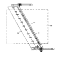
Fig. 1 is the profile according to substrate drying device of the present invention.
Fig. 2 is the profile of the major part of same substrate drying device.
Fig. 3 is the plane of the major part of same substrate drying device.
Description of reference numerals is as follows:
1: substrate drying device, 2: carry roller, 3: opening, 4: loam cake, 5: lower cover, 6: top exhaust apparatus, 7: framework, 8: bottom exhaust apparatus, 9: exhaust cowling panel, 10: the top cowling panel, 11: the top air knife, 12: bottom cowling panel, 13: bottom air knife, 14: the top slip lid, 15: bottom slip lid, W: substrate.
The specific embodiment
Introduce embodiments of the present invention with reference to the accompanying drawings.Fig. 1 is the profile according to substrate drying device of the present invention, and Fig. 2 is the profile of the major part of same substrate drying device, and Fig. 3 is the plane of the major part of same substrate drying device.
In substrate drying device 1, be provided as a plurality of conveying rollers 2 of conveying device, substrate W is transported on the conveying roller 2 from the opening 3 of substrate drying device 1.Carrying roller 2 ... top configuration loam cake 4, carrying roller 2 ... the below lower cover 5 is set, owing to this loam cake 4 and lower cover 5 make the volume of dry place very little.
On described loam cake 4, top exhaust apparatus 6 is set, with respect to lower cover 5 below framework 7 on bottom exhaust apparatus 8 is set. Exhaust apparatus 6,8 for example is the discharge duct that forms exhaust stream.Utilize these top exhaust apparatus 6 and bottom exhaust apparatus 8, in the dry place that between loam cake 4 and lower cover 5, forms with the throughput direction of substrate W be benchmark from the downstream upstream side (Fig. 1 from right to left) form air stream.
In addition, be benchmark with the throughput direction of substrate W, with respect to top exhaust apparatus 6, on the loam cake 4 in downstream, top cowling panel 10 is set.This top cowling panel 10 can adjust upward and can adjust on throughput direction on loam cake 4 at upper and lower.In addition, on plan view, top cowling panel 10 is with respect to the throughput direction tilted configuration of substrate W.
Directly at configuration top, the downstream of described top cowling panel 10 air knife 11.The angle of top air knife 11 be can be on substrate W from upstream the blow side angle of moving air of oblique upper.
On the other hand, on the lower position of the substrate W corresponding, bottom cowling panel 12 and bottom air knife 13 are set with described top cowling panel 10 and top air knife 11, even the varied in thickness of substrate W also will form certain interval, thereby the upper-lower position of described top cowling panel 10 can be adjusted, carry roller 2 in order to be provided with betwixt ..., so form bigger space between below bottom cowling panel 12 and substrate.In addition, the angle of bottom air knife 13 be can be below substrate W below tiltedly the angle of the moving air of side-blown upstream.
In addition, top slip lid 14 and the bottom slip lid 15 that prevents from the air leakage of transport path is being set between loam cake 4 and the top air knife 11 and between lower cover 4 and the bottom air knife 11.
By above-mentioned explanation, the liquid such as rinse water that on be transported to the substrate W that carries on the roller 2, adhere to, by the air from top air knife 11 be pressed into above the substrate and top cowling panel 10 between in the gap that forms, in addition, because top cowling panel 10 tilted configuration, therefore the liquid that is pressed into by the side upstream that forms on substrate and between the top cowling panel 10 air-flow and from the air of top air knife 11 above substrate upstream a side of side be forced out, above substrate W, flow to top exhaust apparatus 6 at last, and discarded in the outside of drying device.
In addition, the liquid that adheres to below substrate W does not flow below substrate W, but falls and flow to bottom exhaust apparatus 8 downwards, and is discarded in the outside of drying device then, so the adhesion amount also constant one-tenth fog that tails off disperses.
According to aforesaid the present invention, configuration top cowling panel above substrate conveying, substrate throughput direction with air below the cowling panel of top and between below the substrate is that the air of side formation upstream flows benchmark from the downstream, because the liquid (cleaning fluid) that adheres on substrate from the pressure of the air of air knife is pressed into below the cowling panel of described top and in the gap between above the substrate, utilize this air stream, above substrate, liquid is extruded at upstream side, therefore reduced from dispersing of the liquid above the substrate, can carry out the drying of substrate.
The result is, liquid does not disperse there to be vaporific form in dry place, and liquid is not attached to the device inner face, reduced the generation of particle thus, improved yield rate.
Claims (8)
1. substrate drying device comprises:
The transport path of substrate;
Discharge the top exhaust apparatus of the air in the transport path;
With the substrate throughput direction be benchmark with respect to described top exhaust apparatus the downstream configuration, and above the substrate between form the top cowling panel in the gap that makes the air upstream side flow; And
Be disposed near this top cowling panel the downstream, on conveying substrate the top air knife of side-jetting air upstream.
2. substrate drying device according to claim 1 further comprises:
Discharge the bottom exhaust apparatus of the air in the transport path;
With the substrate throughput direction be benchmark with respect to described bottom exhaust apparatus the downstream configuration, and substrate below between form the bottom cowling panel in the space that makes the air upstream side flow;
Be disposed near this bottom cowling panel the downstream, below conveying substrate the bottom air knife of side-jetting air upstream.
3. substrate drying device according to claim 1 and 2 is characterized in that described transport path is made of loam cake and lower cover, covers the described top cowling panel that installation can be adjusted upper-lower position last, under cover the bottom cowling panel be installed.
4. substrate drying device according to claim 3 is characterized in that, between described loam cake and the top air knife and between lower cover and the bottom air knife, the top slip lid and the bottom slip lid that prevent from the air diffusion of air knife is set.
5. substrate drying device according to claim 1 and 2, it is characterized in that, near the top exhaust apparatus in described transport path the exhaust cowling panel is set, to prevent from simultaneously to make substrate-levitating from the drop guiding top exhaust apparatus of substrate surface because of the attraction that the top exhaust apparatus produces.
6. substrate drying device according to claim 3, it is characterized in that, near the top exhaust apparatus in described transport path the exhaust cowling panel is set, to prevent from simultaneously to make substrate-levitating from the drop guiding top exhaust apparatus of substrate surface because of the attraction that the top exhaust apparatus produces.
7. substrate drying device according to claim 4, it is characterized in that, near the top exhaust apparatus in described transport path the exhaust cowling panel is set, to prevent from simultaneously to make substrate-levitating from the drop guiding top exhaust apparatus of substrate surface because of the attraction that the top exhaust apparatus produces.
8. drying method for substrate, its application rights requires 1 described substrate drying device that substrate is carried out drying, may further comprise the steps:
With the substrate throughput direction is benchmark, on substrate conveying from the downstream air of tiltedly jetting of inclination upstream, by winding-up air liquid that substrate is adhered to above be pressed into above the substrate and the top cowling panel that above substrate, disposes below between in the gap that forms, the attraction that produces by exhaust apparatus and the power that is pressed into of air knife above substrate upstream side blow walk bulged-in liquid.
Applications Claiming Priority (3)
| Application Number | Priority Date | Filing Date | Title |
|---|---|---|---|
| JP2003184525A JP3865717B2 (en) | 2003-06-27 | 2003-06-27 | Substrate drying apparatus and substrate drying method |
| JP184525/03 | 2003-06-27 | ||
| JP184525/2003 | 2003-06-27 |
Publications (2)
| Publication Number | Publication Date |
|---|---|
| CN1576763A CN1576763A (en) | 2005-02-09 |
| CN100412486C true CN100412486C (en) | 2008-08-20 |
Family
ID=34184261
Family Applications (1)
| Application Number | Title | Priority Date | Filing Date |
|---|---|---|---|
| CNB200410055261XA Active CN100412486C (en) | 2003-06-27 | 2004-06-26 | Substrate drying apparatus and substrate drying method |
Country Status (4)
| Country | Link |
|---|---|
| JP (1) | JP3865717B2 (en) |
| KR (1) | KR101074957B1 (en) |
| CN (1) | CN100412486C (en) |
| TW (1) | TW200504322A (en) |
Families Citing this family (8)
| Publication number | Priority date | Publication date | Assignee | Title |
|---|---|---|---|---|
| JP4494269B2 (en) * | 2005-03-30 | 2010-06-30 | 大日本スクリーン製造株式会社 | Substrate processing equipment |
| JP4679403B2 (en) * | 2006-03-20 | 2011-04-27 | 株式会社日立ハイテクノロジーズ | Substrate drying apparatus, substrate drying method, and substrate manufacturing method |
| KR200452969Y1 (en) * | 2008-12-29 | 2011-04-04 | 주식회사 케이씨텍 | Dryer for large-area substrate |
| JP2013045877A (en) * | 2011-08-24 | 2013-03-04 | Tokyo Electron Ltd | Substrate processing apparatus |
| KR101557021B1 (en) * | 2011-11-07 | 2015-10-02 | (주) 나인테크 | The apparatus for drying the substrate |
| JP6209572B2 (en) * | 2015-01-28 | 2017-10-04 | 芝浦メカトロニクス株式会社 | Substrate processing equipment |
| JP6801926B2 (en) * | 2016-09-26 | 2020-12-16 | 株式会社Screenホールディングス | Substrate processing method and substrate processing equipment |
| KR102498913B1 (en) * | 2021-06-29 | 2023-02-13 | 주식회사 디엠에스 | Dry apparatus of substrate |
Citations (7)
| Publication number | Priority date | Publication date | Assignee | Title |
|---|---|---|---|---|
| JPH0244327U (en) * | 1988-09-20 | 1990-03-27 | ||
| US5014447A (en) * | 1988-02-10 | 1991-05-14 | Thermo Electron Web Systems, Inc. | Positive pressure web floater dryer with parallel flow |
| JPH0735478A (en) * | 1993-07-20 | 1995-02-07 | Shimada Phys & Chem Ind Co Ltd | Air knife device |
| JPH09159360A (en) * | 1995-12-07 | 1997-06-20 | Joichi Takada | Plate type matter drying device |
| JPH11354487A (en) * | 1998-06-03 | 1999-12-24 | Dainippon Screen Mfg Co Ltd | Method and equipment for drying substrate |
| JP2000230783A (en) * | 1999-02-09 | 2000-08-22 | Shibaura Mechatronics Corp | Drying treatment device |
| JP2003124184A (en) * | 2001-10-18 | 2003-04-25 | Sumitomo Precision Prod Co Ltd | Substrate processor |
Family Cites Families (2)
| Publication number | Priority date | Publication date | Assignee | Title |
|---|---|---|---|---|
| JP2983495B2 (en) * | 1997-05-20 | 1999-11-29 | 株式会社カイジョー | Substrate drying method |
| JP3754905B2 (en) * | 2001-09-10 | 2006-03-15 | 東京エレクトロン株式会社 | Substrate dryer |
-
2003
- 2003-06-27 JP JP2003184525A patent/JP3865717B2/en not_active Expired - Lifetime
-
2004
- 2004-06-23 KR KR1020040047143A patent/KR101074957B1/en active IP Right Grant
- 2004-06-25 TW TW093118664A patent/TW200504322A/en unknown
- 2004-06-26 CN CNB200410055261XA patent/CN100412486C/en active Active
Patent Citations (7)
| Publication number | Priority date | Publication date | Assignee | Title |
|---|---|---|---|---|
| US5014447A (en) * | 1988-02-10 | 1991-05-14 | Thermo Electron Web Systems, Inc. | Positive pressure web floater dryer with parallel flow |
| JPH0244327U (en) * | 1988-09-20 | 1990-03-27 | ||
| JPH0735478A (en) * | 1993-07-20 | 1995-02-07 | Shimada Phys & Chem Ind Co Ltd | Air knife device |
| JPH09159360A (en) * | 1995-12-07 | 1997-06-20 | Joichi Takada | Plate type matter drying device |
| JPH11354487A (en) * | 1998-06-03 | 1999-12-24 | Dainippon Screen Mfg Co Ltd | Method and equipment for drying substrate |
| JP2000230783A (en) * | 1999-02-09 | 2000-08-22 | Shibaura Mechatronics Corp | Drying treatment device |
| JP2003124184A (en) * | 2001-10-18 | 2003-04-25 | Sumitomo Precision Prod Co Ltd | Substrate processor |
Also Published As
| Publication number | Publication date |
|---|---|
| KR101074957B1 (en) | 2011-10-18 |
| TWI321641B (en) | 2010-03-11 |
| JP2005016887A (en) | 2005-01-20 |
| TW200504322A (en) | 2005-02-01 |
| CN1576763A (en) | 2005-02-09 |
| JP3865717B2 (en) | 2007-01-10 |
| KR20050001374A (en) | 2005-01-06 |
Similar Documents
| Publication | Publication Date | Title |
|---|---|---|
| US7931755B2 (en) | Method for removing deposit from substrate and method for drying substrate, as well as apparatus for removing deposit from substrate and apparatus for drying substrate using these methods | |
| CN100412486C (en) | Substrate drying apparatus and substrate drying method | |
| CN1325177C (en) | A cleaning device and cleaning method | |
| JP5662473B2 (en) | Filter device, separation device and method for separating paint spray splash | |
| CA2632897A1 (en) | Device and method for the surface treatment of substrates | |
| KR20080042792A (en) | Substrate drying method and substrate drying apparatus | |
| JP2581396B2 (en) | Substrate drying equipment | |
| WO2003071594A1 (en) | Carrier type substrate processing device | |
| JP4932897B2 (en) | Nozzle, dry cleaner and dry cleaner system | |
| JP2001035778A (en) | Substrate treatment apparatus | |
| JP4509613B2 (en) | Substrate processing equipment | |
| JP2000288441A (en) | Spray fluxer device | |
| JP2559349B2 (en) | painting booth | |
| JPH06275506A (en) | Spin coating device and method therefor | |
| JP2004074104A (en) | Conveying and dust removing apparatus | |
| JPH08338686A (en) | Board drying method and device thereof | |
| CN211828692U (en) | Substrate processing apparatus and discharge nozzle | |
| JP3254663B2 (en) | Fine particle injection processing equipment | |
| JPS62183874A (en) | Coating control apparatus | |
| KR20060027597A (en) | Substrate cleaning system and method for cleaning the substrate | |
| JP3971986B2 (en) | Coating apparatus and coating method | |
| KR20160144143A (en) | Substrate processing apparatus | |
| JPH06155012A (en) | Flux applicator | |
| JP2909304B2 (en) | Rotary processing equipment | |
| KR20240002996A (en) | Apparatus for preventing blockage of floating stage, substrate processing equipment and substrate processing method |
Legal Events
| Date | Code | Title | Description |
|---|---|---|---|
| C06 | Publication | ||
| PB01 | Publication | ||
| C10 | Entry into substantive examination | ||
| SE01 | Entry into force of request for substantive examination | ||
| C14 | Grant of patent or utility model | ||
| GR01 | Patent grant |